

PRODUCT
- Fiber optic Terminal box
- Optical distribution Frame
- Outdoor Fiber Distribution Terminal Cabinets
- Data center solution
- Fiber cable managent accessories
- Fiber optic patch cord & pigtail
- Fiber optic adapter
- Fiber optic Attenuator -
-
Fiber Optic splitter
- Fiber Optic Tool
- Fiber Optic Splice Closure
-
J-HOOK
FTTH Termianl box-01 View all products
EK08-F33
Introduction
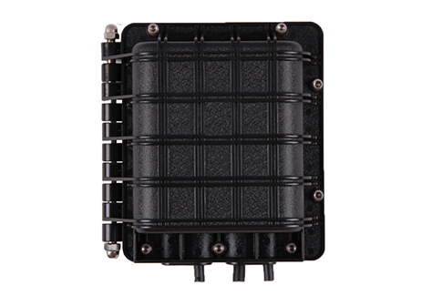
Horizontal Fiber Optic Splice Closure (FOSC)
Multi-functional Fiber Optic Splice Closure (FOSC)
EK08-F33
Installation Manual
1. Scope of application
This Installation Manual is suit for the Fiber Optic Splice Closure (Hereafter abbreviated as FOSC), as the guidance of proper installation. this closure is suit for splitter with adapter or without adapter。
The scope of application is: aerial, underground, pipeline, handhole. The ambient temperature ranges from -40 to 60℃.
2. Basic structure and configuration
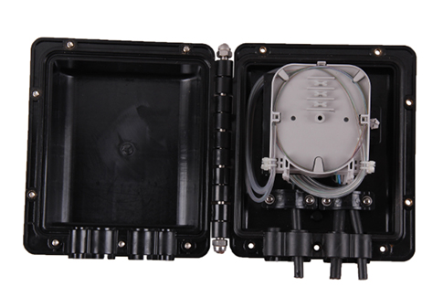
2.1 Product picture
2.2 Dimension and capacity
Outside dimension (L×W×H) | 217×199.5×89 (mm) |
Weight (excluding outside box) | 1000g – 1300g |
Number of inlet/outlet ports | 4 pieces |
Diameter of fiber cable | Φ8—Φ20 (mm) |
Capacity of FOSC | Bunchy: 12—48 (Cores) |
2.3Main components
No. | Name of components | Quantity | Usage | Remarks | |
1 | Housing | 1 set | Protecting fiber cable splices in whole | Internal diameter: | |
2 | Fiber optic splice tray | Max 4 pieces (bunchy) | Fixing heat shrinkable protective sleeve and holding fibers | Suitable for: | |
3 | Seal fitting | 1 set | Sealing between FOSC cover and FOSC bottom |
| |
4 | Port plug | 4 pieces | Sealing empty ports |
| |
5 | Pressure | 1 set | After injecting air, it is used for pressure testing and sealing testing | Configuration as per requirement | |
6 | Earthing deriving device | 1 set | Deriving metallic components of fiber cable in FOSC for earthing connection | Configuration as per requirement | |
2.4 Main accessories and special tools
No. | Name of accessories | Quantity | Usage | Remarks |
1 | Heat shrinkable protective sleeve |
| Protecting fiber splices | Configuration as per capacity |
2 | Nylon tie |
| Fixing fiber with protective coat | Configuration as per capacity |
3 | Insulation tape | 1 roll | Enlarging diameter of fiber cable for easy fixing |
|
4 | Seal tape | 1 roll | Enlarging diameter of fiber cable which fits in with seal fitting | Configuration as per specification |
5 | Hanging hook | 1 set | For aerial use |
|
6 | Earthing wire | 1 piece | Putting through between earthing devices |
|
7 | Abrasive cloth | 1 piece | Scratching fiber cable |
|
8 | Labeling paper | 1 piece | Labeling fiber |
|
9 | Special wrench | 1 piece | Fixing bolts, tightening nut of reinforced core |
|
10 | Measuring paper | 1 piece | To measure circle, of which its diameter is enlarged with seal tape |
|
11 | Buffer tube | To be decided by customers | Hitched to fibers and fixed with FOST, managing buffer | Configuration as per requirement |
12 | Desiccant | 1 bag | Put into FOSC before sealing for desiccating air. |
|
3. Necessary tools for installation
3.1 Supplementary materials (to be provided by operator)
Name of materials | Usage |
Scotch tape | Labeling, temporarily fixing |
Ethyl alcohol | Cleaning |
Gauze | Cleaning |
3.2 Special tools (to be provided by operator)
Name of tools | Usage |
Fiber cutter | Cutting off fibers |
Fiber stripper | Strip off protective coat of fiber cable |
Combo tools | Assembling FOSC |
3.3 Universal tools (to be provided by operator)
Name of tools | Usage and specification |
Band tape | Measuring fiber cable |
Pipe cutter | Cutting fiber cable |
Electrical cutter | Take off protective coat of fiber cable |
Combination pliers | Cutting off reinforced core |
Screwdriver | Crossing/Paralleling screwdriver |
Scissor |
|
Waterproof cover | Waterproof, dustproof |
3.4 Splicing and testing instruments (to be provided by operator)
Name of instruments | Usage and specification |
Fusion Splicing Machine | Fiber splicing |
OT DR | Splicing testing |
Provisional splicing tools | Provisional testing |
Notice: The above-mentioned tools and testing instruments should be provided by the operators themselves.
4. Installation flow chart

5.The process of installing FOSC
5.1Step One - Open the closure
5.1.1 Cleaning the locale and determine where to install the FOSC and then place fiber cables
required.
5.1.2 Check whether the main components and accessories have been well prepared inside
the package.
5.1.3 Open the closure
Unscrew fixing bolts and open the closure by lifting the unscrewed bolts with no need completely unbolting to avoid loosing.
5.1.4 See Drawing 1
Important issues: If the weather condition is not good enough, then a tent must be pitched
for waterproof and dustproof.

5.2 Step Two -Determine length of fiber cable to be fixed and stripped inside FOSC
5.2.1 ①. Fiber cable in 70mm length: the distance from seal fitting to fiber cable pressboard
②. Fiber cable in 800mm length: it is used to be winded and spliced after stripping.
③. Fiber with protective coat in 450mm length: the distance from the fixing point of fiber cable to the fixing point of FOST (fiber optic splice tray).
④. Fiber in 350mm length: after stripping off the protective coat, it is to be winded inside the FOST after splicing with other fibers
5.2.2 See Drawing 2
Important issues:
1.Reserve enough length of fiber cable to be spliced.
2.Stripping length also could be decided by customer according to installation requirement.

5.3 Step Three – Strip off fiber protective coat of fiber cable and fiber
5.3.1 Strip off protective coat of fiber cable from the temp. locating mark with the cutter and the
stripper, please refer to Drawing 2 for stripping length. Stripping length also could be
decided according to installation requirement
5.3.2 See Drawing 3.
Important issues: If it is difficult to pull all the protective coat of fiber cable at one time, strip
it off section by section to avoid fiber breakage.

5.4 Step Four – Separate fiber cores and prepares work prior to fixing fiber.
5.4.1 Wind 2 layers of insulation tape on protective coat of fiber core. Meanwhile, get rid of
the stuffing to separate fiber and clean them. Form a ring with the diameter of 100mm
or so and fix it on the fiber temporarily by adhesive tape.
5.4.2 GJS-6017&5019 is provided with 4 inlet/outlet ports. Among these ports, 2 ports with max. diameter Φ20mm; the remaining 2 ports with max. diameter Φ13mm.
5.4.3 Reserve reinforced core in 85mm length and cut off the unnecessary ones.
5.4.4 See Drawing 4
Important Issues: Cut off reinforced core with special cutting pliers.

5.5 Step Five - Fix reinforced core and fiber cable
5.5.1Remove the plug, pressboard and fixing nut of reinforced core.
5.5.2Tighten the pressboard firmly. If the diameter of fiber cable is not big enough, you could
wrap the insulation tape appropriately.
5.5.3Tighten nut of reinforced core.
5.5.4 See Drawing 5

5.6 Step Six - Splice fibers
5.6.1 Follow user manual of fusion splicing machine to splice fiber cores.
Important issue: pay attention to the twist and bend of fiber.
5.7 Step Seven -Install heat shrinkable protective sleeve and house fibers
5.7.1 When having completed splicing the fibers, the first fiber ring should be housed
on the farthest side of FOST, the remaining fiber should be winded, forming a ring
with diameter not less than 80mm. then put it into FOST (Fiber Optic Splice Tray)
together with heat shrinkable sleeve for splice protection.
( Firstly fix heat shrinkable protective sleeve into the slot, then enlarge the diameter of
fiber ring properly.)
5.7.2 see Drawing 6
Important issue: pay attention to the twist and bend of fiber.

5.8 Step Eight - Check up comprehensively
To ensure the technical requirements, the following instructions must be followed:
5.8.1The fibers in the FOST are spliced and installed orderly. The curved diameter
of fiber meets with the technical requirements.
5.8.2The internal tighteners are tightened.
5.8.3The inlet/outlet ports without fiber cables must be blocked up with the port plugs.
5.8.4Control the amount of seal tape within a proper range.
5.8.5Seal fitting is installed neatly and smoothly.
5.8.6Seal the cover of seal fitting
5.8.7See Drawing 7、Drawing 8


5.9Characteristics
5.9.1The closure is used for splicing part of main fiber cable with branching fiber cable, and meanwhile splicing its rest part with pigtail or drop cable, connecting optical exchange equipment via patchcord. Therefore it saves costs by eliminating splicing unit, distribution unit, distribution box and all the work between fiber optic splice closure and distribution box.
5.9.2It is easy and fast to increase FOST. The SLIDE-IN-LOCK design of FOST with the opening angle 900 makes expansion and maintenance convenient.
5.9.3The distribution unit can have SC adapter front panel to meet with customers various needs. The installation is very easy.
5.9.4Innovative design, easy installation. Based on the advanced formula, the plastic part is made of injection-molded, high-strength engineering plastic PC. It ensures long-term reliability and usage under ambient temperature -40℃- +60℃.
5.9.5The elastic intergrated seal fitting, our patented product, can be reused for many times, it ensures good-resealing performance
5.9.6Multi-functional fiber optic splice closure can be used for wall-mounting and pole-mounting application. It saves the cost for FTTH application and improve quality of telecommunication.
5.10 Step Ten – Assemble FOSC housing
5.10.1 Put the FOSC cover properly.
5.10.2 Insert locating bolt of FOSC and tighten it with the special wrench.
5.10.3 If the FOSC is for aerial application or wall-mounting application, then put the
hanging hook on one side of the closure and then tighten fixing bolts on both sides.
5.10.4 Tight fixing bolt once more properly
5.10.5 See drawing 9
Important issues: cleaning the housing and pay attention to the above sequence.

| Head Company Add:Building 2,No.143 Baihe Rd,Xiangshan Industry Zone,Ningbo city, Zhejiang Province,China Sales department:Tel:+86-574-89526289 Fax:+86-574-89504578 Email: sales@ftthsolution.com info@ftthsolution.com
| Technology Department Tel:+86-574-89504578 Email: technique@ftthsolution.com leixiaoguang@ftthsolution.com After-sale Service Tel:+86-574-89526289 Fax:+86-574-89504578 service hotline:+8613586818063 Email: service @ftthsolution.com info@ftthsolution.com |